Table des matières
Example of border boundary conditions
Click here for the previous page
- This example is defined for a 2D geometrical configuration. The size of the domain is $1.5 \times 1.0.$
- An inlet is located at the down left side of the domain.
- An outlet is located at the top right side of the domain.
- A symmetrical plan is located at the bottom of the domain (Y=0)
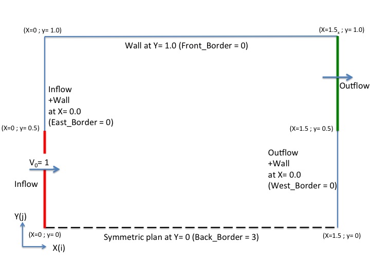
- We remind the user the domain is enclosed by default. Wall boundary conditions are implicitly defined at the ends of the domain.
- The inlet and the outlet are built from the namelists Inlet_Boundary_Condition and Outlet_Boundary_Condition, respectively.
These boundary conditions replace the wall boundary conditions (default) over the areas defined in the namelists.
The inlet and outlets boundary conditions are presented herein for the sake of clarity. - The border boundary condition in accordance with the described configuration are shown just after the inlet/outlet conditions.
Inflow data
- The flow is homogeneous (no multi-species gas)
- Conditions are constant in time
 &Inlet_Boundary_Conditions
 Type_of_BC= "INLET", Direction_Normal_Plan= 1 ,
 Plan_Location_Coordinate= 0.0   ,
 Start_Coordinate_of_First_Span = 0.0, End_Coordinate_of_First_Span = 0.5,
 Start_Coordinate_of_Second_Span= 0.0  , End_Coordinate_of_Second_Span= 0.0 ,
 Flow_Direction= 1 ,
 Normal_Velocity_Reference_Value= 1.0  ,
 Temperature_Reference_Value= 293.0 ,
 Density_Reference_Value=  1.2,
 Define_Velocity_profile= 0 /
Outflow data
- The outflow is based on the mass flowrate conservation.
- The normal pressure gradient is zero (Neumann boundary condition).
&Outlet_Boundary_Conditions
 Type_of_BC= "OUTLET", Direction_Normal_Plan= 1 ,
 Plan_Location_Coordinate= 1.5   ,
 Start_Coordinate_of_First_Span = 0.5    , End_Coordinate_of_First_Span = 1.0 ,
 Start_Coordinate_of_Second_Span= 0.0    , End_Coordinate_of_Second_Span= 0.0 ,
 Flow_Direction= 1 /
Border boundary conditions
- The “BACK” end of the domain must be a symmetric plan.
- The other ends of the domain must be unchanged :
- WEST : Inlet + Wall (by default West_BC_Name= “None”)
- EAST : Outlet + Wall (by default East_BC_Name= “None”)
- FRONT : Wall (the default boundary condition not modified, (by default Front_BC_Name= “None”))
&Border_Domain_Boundary_Conditions Back_BC_Name= "Symmetric" /