Table des matières
Namelist "Velocity_Wall_Boundary_Condition_Setup"
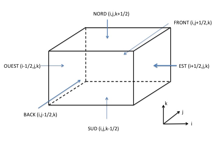
This data setup allow the user to handle the boundary conditions applied to the velocity components on walls. Walls are identified according to the orientation of their normal vector from the adjacent fluid-cell. They are named as :
- WEST : if the wall is located at the i-1/2 face-cell (in regard to a fluid-cell)
- EAST : if the wall is located at the i+1/2 face-cell.
- BACK : if the wall is located at the j-1/2 face-cell.
- FRONT : if the wall is located at the j+1/2 face-cell.
- SOUTH : if the wall is located at the k-1/2 face-cell.
- NORTH : if the wall is located at the k+1/2 face-cell.
A data set can be attributed to the walls of several solid bodies. Some examples are given here .
Full data set of the namelist
 &Velocity_Wall_Boundary_Condition_Setup
  Wall_BC_DataSetName     ="Set1",
  West_Velocity_I_BC_Option = 0  , East_Velocity_I_BC_Option = 0 ,
  Back_Velocity_I_BC_Option = 0  , Front_Velocity_I_BC_Option= 0 ,
  South_Velocity_I_BC_Option= 0  , North_Velocity_I_BC_Option= 0 ,
  West_Velocity_J_BC_Option = 0  , East_Velocity_J_BC_Option= 0 ,
  Back_Velocity_J_BC_Option = 0  , Front_Velocity_J_BC_Option= 0 ,
  South_Velocity_J_BC_Option= 0  , North_Velocity_J_BC_Option= 0 ,
  West_Velocity_K_BC_Option= 0   , East_Velocity_K_BC_Option= 0 ,
  Back_Velocity_K_BC_Option= 0   , Front_Velocity_K_BC_Option= 0 ,
  South_Velocity_K_BC_Option= 0  , North_Velocity_K_BC_Option= 0 ,

  West_Velocity_I_Function_Type = 0, East_Velocity_I_Function_Type= 0,
  Back_Velocity_I_Function_Type = 0, Front_Velocity_I_Function_Type= 0,
  South_Velocity_I_Function_Type= 0, North_Velocity_I_Function_Type= 0 ,
  West_Velocity_J_Function_Type = 0, East_Velocity_J_Function_Type= 0,
  Back_Velocity_J_Function_Type = 0, Front_Velocity_J_Function_Type= 0,
  South_Velocity_J_Function_Type= 0, North_Velocity_J_Function_Type= 0 ,
  West_Velocity_K_Function_Type = 0, East_Velocity_K_Function_Type= 0,
  Back_Velocity_K_Function_Type = 0, Front_Velocity_K_Function_Type= 0,
  South_Velocity_K_Function_Type= 0, North_Velocity_K_Function_Type= 0 ,

  West_Wall_Velocity_I = 0.0   , East_Wall_Velocity_I= 0.0   ,
  Back_Wall_Velocity_I = 0.0   , Front_Wall_Velocity_I= 0.0    ,
  South_Wall_Velocity_I= 0.0   , North_Wall_Velocity_I= 0.0 ,
  West_Wall_Velocity_J= 0.0    , East_Wall_Velocity_J= 0.0   ,
  Back_Wall_Velocity_J= 0.0    , Front_Wall_Velocity_J= 0.0    ,
  South_Wall_Velocity_J= 0.0   , North_Wall_Velocity_J= 0.0 ,
  West_Wall_Velocity_K= 0.0    , East_Wall_Velocity_K= 0.0   ,
  Back_Wall_Velocity_K= 0.0    , Front_Wall_Velocity_K= 0.0    ,
  South_Wall_Velocity_K= 0.0   , North_Wall_Velocity_K= 0.0 /
- The data linked to the velocity components contain the character string “Velocity_I”, “Velocity_J” or “Velocity_K”. These data are thus applied to the velocity component along the I,J or K-direction, respectively.
- When the usual no-slip and impermeability conditions are applied for all walls, this namelist could be omitted in the data file. The code use this boundary condition by default for any wall.
- This namelist can be pooled with other ones of same type (for the heat or species mass fraction) to form a full wall boundary condition setup.
Find here how to construct the wall boundary conditions and some examples.
Definition of the data set
For a sake of clarity, the data are defined for the the “WEST” wall and for the I-velocity component only. The user can easily define the boundary conditions related to the other walls and other velocity components by substituting the relevant character strings in the name of variables.
Wall_BC_DataSetName
- Type : character string
- Name of the data set associated to the wall boundary conditions for the velocity. This name is used as an identifier in order distinguish the different sets of the wall boundary condition defined in the data file. The naming convention adopted is “Set” adjoined with a number : for example “Set1” for the first set, “Set2” for the second one, and so on …
- By default “Set1” is always linked with the walls of domain ends (when they exist). Of course, it can be also linked with any other solid body.
- The same name must be used in the namelists Heat_Wall_Boundary_Condition_Setup (for heat boundary conditions) and Species_Wall_Boundary_Condition_Setup (for species boundary conditions), for building a full wall data set . The user finds here some examples about wall boundary conditions).
- Default value= none
WEST_Velocity_I_BC_Option
- Type : integer value
- Select the type of the boundary condition applied to the I-component and linked to the WEST wall. The available options are :
- 0 : Fixed value
- 1 : Zero gradient
- 2 : Symmetric plan
- Default value = 0
WEST_Velocity_I_Function_Type
- Type : integer value
- Definition of the distribution law over the wall face. The available options are :
- 0 : Uniform distribution over the wall
- greater than 0 : require an user's defined function in the module module_user_define_wall_bc.f90)
- Default value = 0
West_Wall_Velocity_I
- Type : Real value
- Value of the velocity component when the boundary conditions are Dirichlet type.
- Default value = 0.0