Table des matières
Examples of wall boundary conditions
The user finds here some examples illustrating the construction of the wall boundary conditions :
- Heated enclosed cavity : Temperature imposed on sides walls & adiabatic conditions on upper and lower walls
- Two bars in an enclosed cavity : One bar with imposed temperature, the second one with imposed heat flux
- An enclosed cavity with a thermally conductive bar
- A heated bar in a lid-driven cavity
Only 2D geometrical configurations are considered. So, data associated to the 3rd direction K could be removed. They are still kept in these examples even if they are useless.
Some abbreviations considered here :
- WBCT (Wall Boundary Condition Type) refers any namelist describing the type of wall boundary conditions applied to different physical quantities (temperature,velocity, species) :
- The enthalpy or temperature : Namelist "Heat_Wall_Boundary_Condition_Setup"
- The velocity components : Namelist "Velocity_Wall_Boundary_Condition_Setup"
- The species mass fractions : Namelist "Species_Wall_Boundary_Condition_Setup"
- IBD (Immersed Body Descriptor) defines the geometry and the location of the immersed bodies
Heated enclosed cavity
- The domain is a square cavity (2D geometry).
- Bottom and top walls are insulated. The heat flux is null.
- The left wall is set to the upper constant and uniform temperature : T= 305K.
The right wall is set to the lower constant and uniform “temperature : T= 295K. - The velocity boundary conditions are no-slip and impermeability conditions.
- There is no immersed body.
- Walls of the cavity are located at the ends of the domain. This is the basic domain configuration initialized by the code if any other boundary condition is not placed at the ends (like inlet, outlet, symmetrical or periodical boundary conditions)

We need just to set one WPCP.
 &Heat_Wall_Boundary_Condition_Setup
    Wall_BC_DataSetName     ="Set1",
    West_Heat_BC_Option    = 0 ,  East_Heat_BC_Option    = 0 ,  Back_Heat_BC_Option    = 1  ,  Front_Heat_BC_Option    = 1 ,
    South_Heat_BC_Option    = 0 , North_Heat_BC_Option    = 0,
    West_Heat_Function_Type= 0 ,  East_Heat_Function_Type= 0 ,  Back_Heat_Function_Type= 0  ,  Front_Heat_Function_Type= 0 ,
    South_Heat_Function_Type= 0 , North_Heat_Function_Type= 0,
    West_Wall_BC_Value= 305.   ,  East_Wall_BC_Value= 295.  ,  Back_Wall_BC_Value= 0.0   ,  Front_Wall_BC_Value= 0.0   ,
    South_Wall_BC_Value= 0.0   , North_Wall_BC_Value= 0.0  /


    &Velocity_Wall_Boundary_Condition_Setup
    Wall_BC_DataSetName     ="Set1",
    West_Velocity_I_BC_Option= 0 ,  East_Velocity_I_BC_Option= 0 ,  Back_Velocity_I_BC_Option= 0 , Front_Velocity_I_BC_Option= 0,
    South_Velocity_I_BC_Option= 0 , North_Velocity_I_BC_Option= 0 ,
    West_Velocity_J_BC_Option= 0 ,  East_Velocity_J_BC_Option= 0 ,  Back_Velocity_J_BC_Option= 0 , Front_Velocity_J_BC_Option= 0,
    South_Velocity_J_BC_Option= 0 , North_Velocity_J_BC_Option= 0 ,
    West_Velocity_K_BC_Option= 0 ,  East_Velocity_K_BC_Option= 0 ,  Back_Velocity_K_BC_Option= 0 , Front_Velocity_K_BC_Option= 0,
    South_Velocity_K_BC_Option= 0 , North_Velocity_K_BC_Option= 0 ,
    West_Velocity_I_Function_Type= 0,  East_Velocity_I_Function_Type= 0, Back_Velocity_I_Function_Type= 0,
    Front_Velocity_I_Function_Type= 0, South_Velocity_I_Function_Type= 0, North_Velocity_I_Function_Type= 0 ,
    West_Velocity_J_Function_Type= 0,  East_Velocity_J_Function_Type= 0, Back_Velocity_J_Function_Type= 0,
    Front_Velocity_J_Function_Type= 0, South_Velocity_J_Function_Type= 0, North_Velocity_J_Function_Type= 0 ,
    West_Velocity_K_Function_Type= 0,  East_Velocity_K_Function_Type= 0, Back_Velocity_K_Function_Type= 0,
    Front_Velocity_K_Function_Type= 0, South_Velocity_K_Function_Type= 0, North_Velocity_K_Function_Type= 0 ,
    West_Wall_Velocity_I= 0.0   ,   East_Wall_Velocity_I= 0.0   ,   Back_Wall_Velocity_I= 0.0    , Front_Wall_Velocity_I= 0.0   ,
    South_Wall_Velocity_I= 0.0    , North_Wall_Velocity_I= 0.0 ,
    West_Wall_Velocity_J= 0.0   ,   East_Wall_Velocity_J= 0.0   ,   Back_Wall_Velocity_J= 0.0    , Front_Wall_Velocity_J= 0.0   ,
    South_Wall_Velocity_J= 0.0    , North_Wall_Velocity_J= 0.0 ,
    West_Wall_Velocity_K= 0.0   ,   East_Wall_Velocity_K= 0.0   ,   Back_Wall_Velocity_K= 0.0    , Front_Wall_Velocity_K= 0.0  ,
    South_Wall_Velocity_K= 0.0    , North_Wall_Velocity_K= 0.0 /
- There is just one WBCT. This name is “Set1”. It is automatically linked with the walls belonging to the domain ends.
- The no-slip and impermeable boundary conditions are actually used by default in the code. For this reason, this kind of boundary conditions could be not explicitly set.
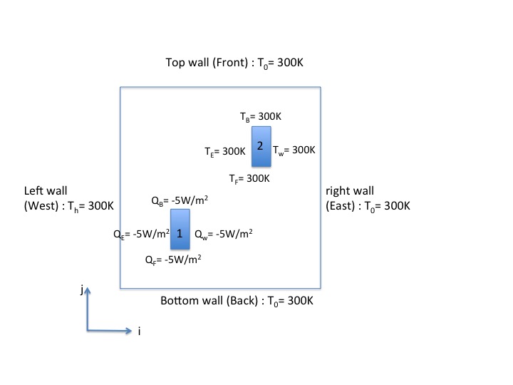
Two bars in an enclosed cavity
- The domain is a square cavity with a length of $L= 1.0$ (2D geometry).
- Walls of the cavity are set to the constant and uniform temperature : $T= 300 K$.
- Walls of the first bar are set to the constant and uniform heat flux : $Q= 5W/m^2$. Keep in mind that :
- heating the fluid from walls is defined with a negative heat flux
- cooling the fluid from walls is defined with a positive heat flux
- Walls of the second bar are set to the same boundary conditions as the cavity : $T=300 K$.
- The velocity boundary conditions are no-slip and impermeability conditions for all the walls (cavity and bars). As they correspond to the default boundary conditions, they are not explicitly set here.
- There are two immersed bodies : the couple of bars. Each bar is a rectangle with a size of $0.1$x$0.2$. The center of the first bar is $0.3$x$0.3$, the second one is $0.7$x$0.7$
 We need two WBCT for setting the two different sets of wall boundary conditions, the first one for the imposed temperature, the second one for the imposed heat flux. We also need to set two IBD in order to define the positions of the couple of bars.
The first WBCT
  &Heat_Wall_Boundary_Condition_Setup
   Wall_BC_DataSetName     ="Set1",
    West_Heat_BC_Option    = 0 ,  East_Heat_BC_Option    = 0 ,  Back_Heat_BC_Option    = 0  ,  Front_Heat_BC_Option    = 0 , South_Heat_BC_Option    = 0 , North_Heat_BC_Option    = 0,
    West_Heat_Function_Type= 0 ,  East_Heat_Function_Type= 0 ,  Back_Heat_Function_Type= 0  ,  Front_Heat_Function_Type= 0 , South_Heat_Function_Type= 0 , North_Heat_Function_Type= 0,
    West_Wall_BC_Value= 300.   ,  East_Wall_BC_Value= 300.  ,  Back_Wall_BC_Value= 300.0   ,  Front_Wall_BC_Value= 300.0   , South_Wall_BC_Value= 0.0   , North_Wall_BC_Value= 0.0  /
The second WBCT
  &Heat_Wall_Boundary_Condition_Setup
   Wall_BC_DataSetName     ="Set2",
    West_Heat_BC_Option    = 1 ,  East_Heat_BC_Option    = 1 ,  Back_Heat_BC_Option    = 1  ,  Front_Heat_BC_Option    = 1 , South_Heat_BC_Option    = 0 , North_Heat_BC_Option    = 0,
    West_Heat_Function_Type= 0 ,  East_Heat_Function_Type= 0 ,  Back_Heat_Function_Type= 0  ,  Front_Heat_Function_Type= 0 , South_Heat_Function_Type= 0 , North_Heat_Function_Type= 0,
    West_Wall_BC_Value= -5.0   ,  East_Wall_BC_Value= -5.0  ,  Back_Wall_BC_Value= -5.0  ,  Front_Wall_BC_Value= -5.0  , South_Wall_BC_Value= 0.0   , North_Wall_BC_Value= 0.0  /
The first IBD (the first bar)
 &Polyhedral_Immersed_Bodies
     Xi_1= 0.25 , Xj_1= 0.20 , Xk_1= 0.0 ,
     Xi_2= 0.35 , Xj_2= 0.20 , Xk_2= 0.0 ,
     Xi_3= 0.35 , Xj_3= 0.40 , Xk_3= 0.0 ,
     Xi_4= 0.25 , Xj_4= 0.40 , Xk_4= 0.0 ,
     Wall_BC_DataSetName     ="Set2"/
The second IBD (the second bar)
 &Polyhedral_Immersed_Bodies
     Xi_1= 0.65 , Xj_1= 0.60 , Xk_1= 0.0 ,
     Xi_2= 0.75 , Xj_2= 0.60 , Xk_2= 0.0 ,
     Xi_3= 0.75 , Xj_3= 0.80 , Xk_3= 0.0 ,
     Xi_4= 0.65 , Xj_4= 0.80 , Xk_4= 0.0 ,
     Wall_BC_DataSetName     ="Set1"/
- The first immersed body is linked to the second WBCT(imposed heat flux) and the second body is linked to the first WBCT (imposed temperature) by means of the variable “Wall_BC_DataSetName”.
- The WBCT named “Set1” is also automatically linked to the walls of the domain end's (cavity walls).
- The rank order of the boundary conditions is unimportant.
- About imposed heat flux, keep in mind that :
- heating the fluid from walls is defined with a negative heat flux
- cooling the fluid from walls is defined with a positive heat flux
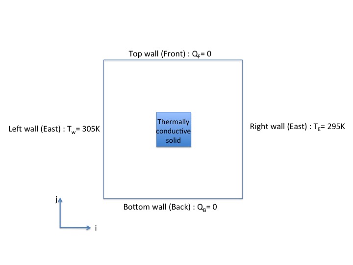
Enclosed cavity with a thermally conductive bar
- The domain is a square cavity with a length of $L= 1.0$ (2D geometry).
- Bottom and top walls of the cavity are insulated. The heat flux is null.
- The left and right walls of the cavity are set to 305K and 295K, respectively.
- The bar is thermally conductive. Its size is $0.2$x$0.2$ and it is centered on the cavity.
- The velocity boundary conditions are no-slip and impermeable conditions for all walls.
We need to set two WBCT to define the two different sets of wall boundary conditions, the first one for the imposed temperature and heat flux at the walls of the cavity, the second one to define the physical properties of the bar. We also need to set one IBD in order to define the position of the bar.
The first WBCT
  &Heat_Wall_Boundary_Condition_Setup
    Wall_BC_DataSetName     ="Set1",
    West_Heat_BC_Option    = 0 ,  East_Heat_BC_Option    = 0 ,  Back_Heat_BC_Option    = 1  ,  Front_Heat_BC_Option    = 1 , South_Heat_BC_Option    = 0 , North_Heat_BC_Option    = 0,
    West_Heat_Function_Type= 0 ,  East_Heat_Function_Type= 0 ,  Back_Heat_Function_Type= 0  ,  Front_Heat_Function_Type= 0 , South_Heat_Function_Type= 0 , North_Heat_Function_Type= 0,
    West_Wall_BC_Value= 305.   ,  East_Wall_BC_Value= 295.  ,  Back_Wall_BC_Value= 0.0   ,  Front_Wall_BC_Value= 0.0   , South_Wall_BC_Value= 0.0   , North_Wall_BC_Value= 0.0  /
The second WBCT
  &Heat_Wall_Boundary_Condition_Setup
    Wall_BC_DataSetName     ="Set2",
    West_Heat_BC_Option    = 2 ,  East_Heat_BC_Option    = 2 ,  Back_Heat_BC_Option    = 2  ,  Front_Heat_BC_Option    = 2 ,
    South_Heat_BC_Option    = 0 , North_Heat_BC_Option    = 0,
    Material_Thermal_Conductivity= 1.00 , Material_Mass_Heat_Capacity= 3000.00 , Material_Density= 900.00 /
The first IBD (the bar)
 &Polyhedral_Immersed_Bodies
     Xi_1= 0.40 , Xj_1= 0.40 , Xk_1= 0.0 ,
     Xi_2= 0.40 , Xj_2= 0.40 , Xk_2= 0.0 ,
     Xi_3= 0.60 , Xj_3= 0.60 , Xk_3= 0.0 ,
     Xi_4= 0.60 , Xj_4= 0.60 , Xk_4= 0.0 ,
     Wall_BC_DataSetName     ="Set2"/
- The WBCT named “Set1” is automatically linked to the walls of the domain end's (cavity walls).
- The bar (immersed body) is linked to the second WBCT.
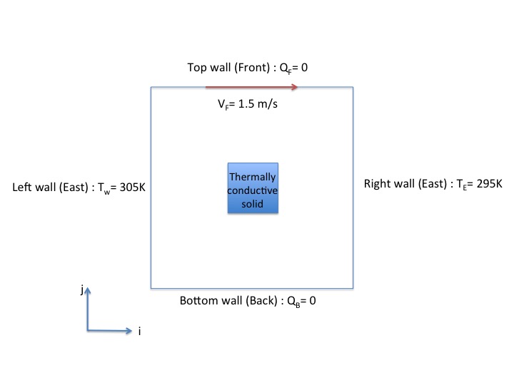
Heated bar in a lid-driven cavity
The example is very similar to the previous one but the fluid is driven by the top wall of the cavity.
- The domain is a square cavity with a length of $L= 1.0$ (2D geometry).
- Bottom and top walls of the cavity are insulated. The heat flux is null.
- The left and right walls of the cavity are set to 305K and 295K, respectively.
- The bar is thermally conductive. Its size is $0.2$x$0.2$ and it is centered on the cavity.
- The velocity boundary conditions are no-slip and impermeability conditions for all walls except at the top of the cavity where $V= 1.5m.s^{-1}$. For these reason, the wall boundary conditions for the velocity must be set.
We need to set two WBCT to define the two different sets of wall boundary conditions, the first one for the imposed temperature and heat flux at the walls of the cavity, the second one to define the physical properties of the bar. We also need to set one IBD in order to define the position of the bar.
The first WBCT
  &Heat_Wall_Boundary_Condition_Setup
    West_Heat_BC_Option    = 0 ,  East_Heat_BC_Option    = 0 ,  Back_Heat_BC_Option    = 1  ,  Front_Heat_BC_Option    = 1 , South_Heat_BC_Option    = 0 , North_Heat_BC_Option    = 0,
    West_Heat_Function_Type= 0 ,  East_Heat_Function_Type= 0 ,  Back_Heat_Function_Type= 0  ,  Front_Heat_Function_Type= 0 , South_Heat_Function_Type= 0 , North_Heat_Function_Type= 0,
    West_Wall_BC_Value= 305.   ,  East_Wall_BC_Value= 295.  ,  Back_Wall_BC_Value= 0.0   ,  Front_Wall_BC_Value= 0.0   , South_Wall_BC_Value= 0.0   , North_Wall_BC_Value= 0.0  /

   &Velocity_Wall_Boundary_Condition_Setup
    West_Velocity_I_BC_Option= 0 ,  East_Velocity_I_BC_Option= 0 ,  Back_Velocity_I_BC_Option= 0 , Front_Velocity_I_BC_Option= 0,
    South_Velocity_I_BC_Option= 0 , North_Velocity_I_BC_Option= 0 ,
    West_Velocity_J_BC_Option= 0 ,  East_Velocity_J_BC_Option= 0 ,  Back_Velocity_J_BC_Option= 0 , Front_Velocity_J_BC_Option= 0,
    South_Velocity_J_BC_Option= 0 , North_Velocity_J_BC_Option= 0 ,
    West_Velocity_K_BC_Option= 0 ,  East_Velocity_K_BC_Option= 0 ,  Back_Velocity_K_BC_Option= 0 , Front_Velocity_K_BC_Option= 0,
    South_Velocity_K_BC_Option= 0 , North_Velocity_K_BC_Option= 0 ,
    West_Velocity_I_Function_Type= 0,  East_Velocity_I_Function_Type= 0, Back_Velocity_I_Function_Type= 0,
    Front_Velocity_I_Function_Type= 0, South_Velocity_I_Function_Type= 0, North_Velocity_I_Function_Type= 0 ,
    West_Velocity_J_Function_Type= 0,  East_Velocity_J_Function_Type= 0, Back_Velocity_J_Function_Type= 0,
    Front_Velocity_J_Function_Type= 0, South_Velocity_J_Function_Type= 0, North_Velocity_J_Function_Type= 0 ,
    West_Velocity_K_Function_Type= 0,  East_Velocity_K_Function_Type= 0, Back_Velocity_K_Function_Type= 0,
    Front_Velocity_K_Function_Type= 0, South_Velocity_K_Function_Type= 0, North_Velocity_K_Function_Type= 0 ,
    West_Wall_Velocity_I= 0.0   ,   East_Wall_Velocity_I= 0.0   ,   Back_Wall_Velocity_I= 0.0    , Front_Wall_Velocity_I= 1.5   ,
    South_Wall_Velocity_I= 0.0    , North_Wall_Velocity_I= 0.0 ,
    West_Wall_Velocity_J= 0.0   ,   East_Wall_Velocity_J= 0.0   ,   Back_Wall_Velocity_J= 0.0    , Front_Wall_Velocity_J= 0.0   ,
    South_Wall_Velocity_J= 0.0    , North_Wall_Velocity_J= 0.0 ,
    West_Wall_Velocity_K= 0.0   ,   East_Wall_Velocity_K= 0.0   ,   Back_Wall_Velocity_K= 0.0    , Front_Wall_Velocity_K= 0.0  ,
    South_Wall_Velocity_K= 0.0    , North_Wall_Velocity_K= 0.0 /
The second WBCT
  &Heat_Wall_Boundary_Condition_Setup
  West_Heat_BC_Option    = 2 ,  East_Heat_BC_Option    = 2 ,  Back_Heat_BC_Option    = 2  ,  Front_Heat_BC_Option    = 2 ,
  South_Heat_BC_Option    = 0 , North_Heat_BC_Option    = 0,
    Material_Thermal_Conductivity= 1.00 , Material_Mass_Heat_Capacity= 3000.00 , Material_Density= 900.00 /

    &Velocity_Wall_Boundary_Condition_Setup
    West_Velocity_I_BC_Option= 0 ,  East_Velocity_I_BC_Option= 0 ,  Back_Velocity_I_BC_Option= 0 , Front_Velocity_I_BC_Option= 0,
    South_Velocity_I_BC_Option= 0 , North_Velocity_I_BC_Option= 0 ,
    West_Velocity_J_BC_Option= 0 ,  East_Velocity_J_BC_Option= 0 ,  Back_Velocity_J_BC_Option= 0 , Front_Velocity_J_BC_Option= 0,
    South_Velocity_J_BC_Option= 0 , North_Velocity_J_BC_Option= 0 ,
    West_Velocity_K_BC_Option= 0 ,  East_Velocity_K_BC_Option= 0 ,  Back_Velocity_K_BC_Option= 0 , Front_Velocity_K_BC_Option= 0,
    South_Velocity_K_BC_Option= 0 , North_Velocity_K_BC_Option= 0 ,
    West_Velocity_I_Function_Type= 0,  East_Velocity_I_Function_Type= 0, Back_Velocity_I_Function_Type= 0,
    Front_Velocity_I_Function_Type= 0, South_Velocity_I_Function_Type= 0, North_Velocity_I_Function_Type= 0 ,
    West_Velocity_J_Function_Type= 0,  East_Velocity_J_Function_Type= 0, Back_Velocity_J_Function_Type= 0,
    Front_Velocity_J_Function_Type= 0, South_Velocity_J_Function_Type= 0, North_Velocity_J_Function_Type= 0 ,
    West_Velocity_K_Function_Type= 0,  East_Velocity_K_Function_Type= 0, Back_Velocity_K_Function_Type= 0,
    Front_Velocity_K_Function_Type= 0, South_Velocity_K_Function_Type= 0, North_Velocity_K_Function_Type= 0 ,
    West_Wall_Velocity_I= 0.0   ,   East_Wall_Velocity_I= 0.0   ,   Back_Wall_Velocity_I= 0.0    , Front_Wall_Velocity_I= 0.0   ,
    South_Wall_Velocity_I= 0.0    , North_Wall_Velocity_I= 0.0 ,
    West_Wall_Velocity_J= 0.0   ,   East_Wall_Velocity_J= 0.0   ,   Back_Wall_Velocity_J= 0.0    , Front_Wall_Velocity_J= 0.0   ,
    South_Wall_Velocity_J= 0.0    , North_Wall_Velocity_J= 0.0 ,
    West_Wall_Velocity_K= 0.0   ,   East_Wall_Velocity_K= 0.0   ,   Back_Wall_Velocity_K= 0.0    , Front_Wall_Velocity_K= 0.0  ,
    South_Wall_Velocity_K= 0.0    , North_Wall_Velocity_K= 0.0 ,
   End_of_Data_Block= .true. /
The first IBD (the bar)
 &Polyhedral_Immersed_Bodies
     Xi_1= 0.40 , Xj_1= 0.40 , Xk_1= 0.0 ,
     Xi_2= 0.40 , Xj_2= 0.40 , Xk_2= 0.0 ,
     Xi_3= 0.60 , Xj_3= 0.60 , Xk_3= 0.0 ,
     Xi_4= 0.60 , Xj_4= 0.60 , Xk_4= 0.0 ,
     Wall_BC_DataSetName     ="Set2"/
- The first WBCT is automatically linked to the walls of the domain end's (cavity walls). The wall temperatures are imposed as in the previous case. Moreover the I-velocity component is set to 1.5 at the top wall (Front_Wall_Velocity_I= 1.5).
- The bar (immersed body) is linked to the second WBCT. The usual no-slip and impermeability boundary conditions are explicitly set here because the default values are no longer available due to the previous WBCT.
- When several WBCT are present and at least one of them contains a specific set of velocity boundary conditions, which differ from the usual ones, the namelist "Velocity_Wall_Boundary_Condition_Setup" must then be explicitly set for each WBCT, even for the usual velocity boundary conditions.
Click here to come back to the "Heat_Wall_Boundary_Condition_Setup"
Click here to come back to the "Velocity_Wall_Boundary_Condition_Setup"
Click here to come back to the "Species_Wall_Boundary_Condition_Setup"
Click here to come back to the "Polyhedral_Immersed_Bodies"
Click here to come back to the "Cylindrical_Immersed_Bodies"
- fr